Anaerobic Workstations

For Product Catalog Click here: Anaerobic Workstations

The Anaerobic Workstation/ Anaerobic Chamber has to replicate conditions where anaerobes will grow.

Firstly, the human body has a temperature of around 36.5 degrees centigrade and the heating system of the workstation must be stable at this temperature.
Remember, that the human body kills unwanted bacteria by lifting its temperature just a few degrees.
However, this is not the only temperature that the scientists may be interested in, and therefore the workstation must be capable of operating at other temperatures.
The lowest temperature that the standard MUNRO(Electrotek) workstation will operate at is 4 degrees centigrade above the ambient temperature.
The highest temperature that the standard MUNRO(Electrotek) workstation will operate at is 45 degrees centigrade.
This higher temperature is suitable for microaerophilic bacteria that require some oxygen presence.
To grow these microaerophilic bacteria a special gas supply is required where a small percentage of oxygen is needed and the catalyst is no longer used.
The next consideration must be the atmosphere within the incubation section of the workstation; the MUNRO(Electrotek) workstation uses a mixed gas supply for the bacterial growth.
This mixed gas is obtainable from the laboratory gas suppliers such as BOC.or AIRPRODUCTS
This mixed gas however is relatively expensive but the standard mix is considered safe.
Some anaerobic cabinet manufacturers have offered a gas mixing system to reduce the operating cost of the workstation.
In some areas of the world Mixed Anaerobic Gas is not available.
MUNRO have always rejected this approach on the grounds of operating safety and have taken precautions to prevent the potential danger.
Some customers have requested a gas mixture from us that is not the standard mixture and asked for a mixture with a reduced hydrogen content on the grounds of safety.
We have supplied these Workstations.
The problem here is that there is a potential problem of hydrogen starvation within the incubator.
The standard Anaerobic Gas Mixture is : 10% H2 + 10% CO2 + 80% N2
The low hydrogen Anaerobic Gas Mixture is : 5% H2 + 10% CO2 + 85% N2
Let us look at each of these gasses in turn:
N2, This is only a filler gas to make up the volume.
C02, This is a stimulant for the bacteria, remember the primitive origins of anaerobes.
H2, This is the gas that gets the workstation oxygen free, but remember its potential danger with a 4% . Lower Explosive Limit (LEL) in air.
Now, hydrogen will separate from the other gasses and rise to the top if left in a confined space and can be ignited and explode with the tiniest spark, ie by operating a switch or relay.
Therefore, the workmanship within the control section must be of a very high standard and all the joints must be gas tight to prevent a leak of the mixed gas.

Anaerobic Workstations

Bacterial Growth

The bacteria are grown in Petri dishes that are partly filled with a jelly like media.
Once the media is set and cooled the bacterial samples are coated onto the top of the jelly, then a vented lid is placed onto the Petri dish.
The media contains a suitable nutrient to encourage bacterial growth.
Note! Some air containing 20% 02 will be trapped between the lid and the media.
The Petri dishes are incubated upside down. ie Lids on the bottom.
Another source of oxygen can come from the dissolved oxygen in the media itself, unless the media has been pre-reduced.
On the AW400/500 it is therefore calculable how much O2 is being admitted into the workstation with each Lock Flush.
This O2 will eventually be converted into water by combining it with the hydrogen in the mixed gas that has been injected into the incubator during the Lock Flush.
Twice as much hydrogen will be used than the oxygen that has to be removed since water is H2O.
The Petri dishes will enter the incubator at about 20 degrees centigrade and over a period warm up to 36.5 degrees centigrade.
This will cause the media to start giving off water vapour and this together with diffusion and gas circulation will remove the O2 from beneath the vented Petri dish lids.
Some of this water vapour will condense onto the Petri Dish Lids and prevent the water droplets spoiling the growth of the bacteria.
Over about a period of about a week the media will completely dry out and this evaporation will end up inside the incubator, this excess has to be removed.
The workstation is fitted with a humidistat to control the humidity level and this is usually set at 70% RH.
When the humidity exceeds the 70% RH level, a fan is switched on and blows air from the laboratory onto a cooling plate that is fitted to the endplate of the incubator. Now the air in the laboratory is likely to be at a temperature of around 20 degrees centigrade and this is about 15 degrees centigrade lower than the temperature in the incubator. This causes the water vapour in the incubator to condense on the cool plate face, run down and be collected in the water collection bottle.

Anaerobic Workstations

Anaerobic Workstations

How is the Workstation made anaerobic and then kept anaerobic.?

Quite simply because the workstation is fitted with a palladium catalyst and it is supplied with hydrogen and it always has enough hydrogen to mop up any oxygen that enters the workstation.
When the workstation arrives at the laboratory the incubator is full of air, this air contains 20% oxygen and this oxygen must be removed.
If a volume is full of air and is flushed out once by its own volume we would expect half of the oxygen to be removed, if it is flushed out four times we would expect the oxygen level to be down to 1.25 %.
This is exactly what we do during the “Commissioning Process” we flush four times the volume of the incubator with mixed gas and let the catalyst remove the remainder of the oxygen.
During commissioning the front of the incubator gets covered with condensation this shows that the catalyst is working. The workstation will slowly remove this condensation.
The commissioning takes approximately ¾ of an hour.
The very same logic is applied when the interlock is flushed to either admit or remove stacks of Petri dishes into or out of the incubator.
The palladium catalysts sachet that links the unwanted oxygen and the hydrogen together is situated beneath the bottom shelf of the incubator and another catalyst sachet is fitted into the roof of the interlock.
The catalyst sachet gets hot during commissioning.
Once the anaerobic bacteria starts growing they produce hydrogen sulphide, this smells like rotten eggs and also volatile fatty acids
These are poisonous to the catalyst and prevent it working.
The sachet of catalyst inside the incubator is protected by a sachet of Activated Carbon that mops up both these poisons. (This is called the Conditioner)
The mixed gas inside the incubator must first pass over the sachet of Conditioner before it is allowed to pass over the Sachet of Catalyst.
Therefore the Conditioner Sachet fitted beneath the shelf is at back and the Catalyst Sachet is at the front.
Now the Workstation is supplied with gas from a gas cylinder, this size L cylinder contains 9.3 cubic metres of free gas when it is fully charged. The approximate volume of any MUNRO(Electrotek) workstation is about one litre per Perti dish, therefore an AW500 workstation will have a volume of approximately 500 litres.
The commissioning of the AW500 will use approximately 2 cubic metres of the 9.3 cubic metres of mixed gas available.
Once the commissioning is complete it is important that the commissioning switch is put back manually into its normal operating position.
It will now become clear that since the 2 cubic metres of mixed gas is flushed into the laboratory via the interlock we recommend that the laboratory be well ventilated.Providing that the incubator is never starved of hydrogen the catalyst will reduce the oxygen levels down to just a few parts per million.

Anaerobic Workstations

The Interlock

The MUNRO(Electrotek) AW400 and AW500 interlock will hold 60 Petri dishes and these dishes can be transferred into and out of the incubator without significantly affecting the anaerobic conditions within the incubator.

Once the Interlock has been loaded up with the Petri dishes for insertion into the incubator the Lock Flush procedure can be started by pressing the “Start Lock Flush“ button on the control panel.

The purpose of flushing the interlock is to prevent oxygen getting into the incubator.

The interlock is fitted with a sachet of Catalyst to assist with the oxygen removal.

This catalyst generates some water into the interlock but this is minimal

There is no need to fit a Conditioner sachet since bacterial growth will be minimal and catalytic poisoning is not a problem.

The lock flushing will commence providing that all the gasses needed are available at the correct inlet pressure and both the interlock doors are fully closed.

Neon indicators on the control panel show if the gasses are available and if the doors are fully closed.

When the lock flushing commences this is also indicated on the control panel.

The interlock flushing takes 5 minutes to complete.

During this period gas is passed through the interlock in pulses.

Each pulse takes 6 seconds to complete with gas flowing for 4 seconds then a 2 second rest period.

At the end of the flushing period an indicator on the control panel shows that the flush cycle is complete.

The inner door of the interlock can now be opened and the Petri dishes transferred into the incubator.

In the AW400SG and the AW500SG models the interlock is flushed with the mixed gas only.

Here the mixed gas is first injected into the incubator where it freshens up the gasses before it is passed into the interlock for flushing purposes.

However as previously mentioned the mixed gas is very expensive.

The AW400TG and the AW500TG models use a slightly different approach to reduce the running cost of the workstations.

Here the interlock is flushed directly for the first 3 minutes by cheap oxygen free nitrogen before it is switched over to complete its flush cycle with mixed anaerobic gas.

The interlock flushing should be the main area where the mixed gas is consumed.

Removal of Petri dishes from the workstation

Providing that the interlock is anaerobic, and this is shown inside the incubator by a large neon indicator the Petri dishes can be removed from the incubator by placing them back into the interlock through the interlock inner door, this door is then closed and the outer door is opened and the dishes are taken out of the interlock.

The interlock is once again aerobic

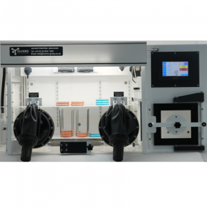
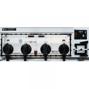
The Single Plate Entry tunnel

Sometimes it is necessary for an operator to insert just a single Petri dish into the incubator.

This can be in a hospital late at night when an operator unfamiliar with the workstation is required to insert a single plate into the incubator.

The small single plate entry door is quickly opened and the single plate is pushed into the incubator and the door quickly closed.

Note the design, here the single plate entry tunnel is fitted with a hinged door at the back to prevent excessive escape of gas and a ramp that removes and then replaces the Petri dish lid whilst it is being inserted into the incubator. The lifted lid allows the escaping anaerobic gas to blow out the unwanted oxygen trapped beneath the Petri dish lid.

Secondly, the inside of the incubator is held at a positive pressure of 100 Pascals to prevent any oxygen getting into the unit, therefore gas escapes from the incubator during the small time that the single plate entry door is open, prevents any oxygen penetration.

This single plate entry system is a major gas saver for the insertion of a small numbers of dishes.
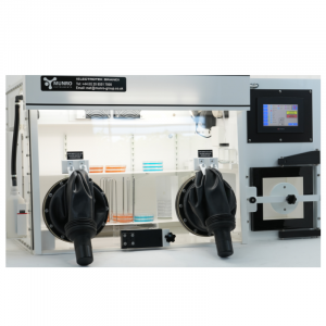
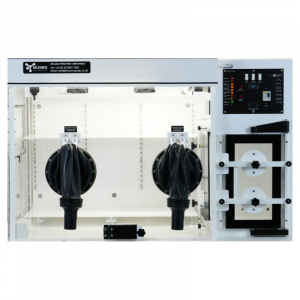
The Gauntlets

The MUNRO(Electrotek) workstation can be used with bare hands with detachable cuffs that are attached to the gauntlets forming the gas seal around the wrists,

Some operators are sensitive to the latex in the standard wrist cuffs and here we can supply neoprene cuffs to overcome this problem.

These neoprene cuffs are much more expensive and much less flexible.

Some applications require glove working within the incubator and here flexible gloves can be attached to the gauntlets in the usual manner.
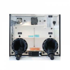
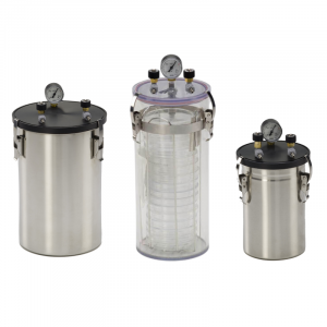
The Bubble Bottle

A bubble bottle is fitted to the endplate of the incubator, this bottle has three functions.

1) It allows the arms to be inserted into the incubator

2) It allows the low internal gas pressure to be maintained

3) It acts as a safety valve for the incubator in the event of the Mixed Gas inlet solenoid remaining open.

Gas leaks

Once the workstation passes its inspection there should be no gas leaks, however these will occur during its working life.

If the gas leak is serious then the cabinet will sense the fault and close the inlet mixed gas solenoid after a period of 2 minutes of continuous gas flow.

A neon indicator on the control panel shows the problem and a buzzer is activated.
Unless the mixed gas solenoid is closed down the whole cylinder of gas would be emptied into the laboratory

This kind of leak is usually caused by the operator not checking the water level in the Bubble Bottle over a lengthy period, but is very easily cured by adding more water to the bottle.

The other causes of a gas leak are a damaged gauntlet or cuff or a damaged door seal.

These are the things to check during a routine maintenance visit.

The O Rings attaching the gauntlet assemblies together are affected by sunlight and show cracks on their surface. At this stage the O Rings should be replaced.

Searching for leaks during the test and inspection

If the fabrication of the workstation shell and the assembly have been carefully performed, leaks are not a major problem.

However if there is a leak it can sometimes be difficult to find.

Leaks can occur in both the incubator and in the control side of the workstation

Earlier we discussed the problems associated with leaks in the control section of the unit.

Leaks in the control side can be observed by watching for pressure drops or with the liquid leak detector.

The Gas Leak Detector cannot be used during initial testing because the inlet gas to the cabinet does not have any thing in it that the Gas Leak Detector can sense.

If a gas leak is suspected and mixed gas is being used, the Gas Leak Detector could then be used to find the leak.

The Liquid Leak detector is useful but care must be taken if it is used near electrical components.

If the leak in the incubator is not stopped after checking the screws and cable glands, then a Gas Leak Detector that is sensitive to alcohol and a swab soaked in alcohol can be used.

The swab soaked in alcohol is placed inside the sealed incubator.

This may seem to stop the leak but all that is happening is that the alcohol vapour is filling the space lost by the leak.

I would urge caution here, the alcohol vapour is likely to be explosive so take out the heater fuse and only use the LED tube light for illumination.

Now switch on the Gas Leak Detector, let it settle down and then start searching for the leak by listening for the increased frequency of its output tone as the sensor is moved around the outside of the workstation.

Checking for anaerobic condition within the incubator

There are at least four methods of checking for good anaerobic conditions within the incubator.

1) MUNRO(Electrotek) supplies a pump that passes the atmosphere within the workstation through a chemical solution.

Here a colour change takes place from clear to blue at just a few parts of oxygen per million.

If the bottle containing this indicator is placed in a bath of water and the water is brought to the boil the oxygen will be boiled out of the indicator and its blue colour will change to clear.

However, the indicator must be removed from the boiling water immediately it changes colour or the sugar will start to caramelise and turn the indicator to brown.

This trick is very useful when the cabinet is being commissioned.

The indicator changes from clear to blue very quickly but takes a much longer time to change the other way.

We recommend that the MUNRO(Electrotek) indicator solution pump be switched on for just a brief period each day.

We also recommend that the indicator solution is changed each week and that any unused indicator is kept refrigerated at 4 degrees centigrade

2) Sealed strips soaked in a chemical can be purchased that change colour in the presence of oxygen.

3) The microbiologist can grow control cultures that should grow and should not grow in the workstation.

4) Electronic Sensors

The control panel

The control panel is very simple, it consists of:

1) An earth leakage circuit breaker (ELCB). This protects the operator from a serious electric shock.
2) 7 Fuses to protect the electrics within the workstation
3) 2 Push Buttons One to start the Lock Flush, the other to Silence the Alarms
4) Indicator neon’s to show the state of the workstation
5) 4 Switches. These control the Lights, Sockets and Commissioning.
6) Temperature Controller
7) Battery Holder. Powers a Buzzer if the power is switched OFF


For Product Catalog Click here:: Anaerobic Workstations